-
CN
-
Service Hotline
+8618129931046 Mr. Liao


Time:2025-04-15 Views:1

There are two main component mounting methods in PCBA: through - hole mounting and surface - mount mounting. Through - hole mounting, as mentioned before, involves inserting component leads through holes in the PCB. This method offers several advantages. It provides a strong mechanical connection, making it suitable for components that may be subject to mechanical stress, such as power connectors. Components with large form factors or high - current requirements are often through - hole mounted. However, through - hole mounting takes up more space on the PCB, which can limit the overall component density.
Surface - mount mounting, in contrast, allows for a much higher component density. Surface - mount components are smaller in size and are mounted directly on the surface of the PCB. This not only saves space but also reduces the length of electrical connections, which can improve electrical performance, especially for high - frequency signals. Surface - mount components are available in a wide range of packages, including small outline integrated circuits (SOICs), quad flat packages (QFPs), and ball grid arrays (BGAs). BGAs, for example, have a large number of solder balls on the bottom of the package, providing a high - density connection.
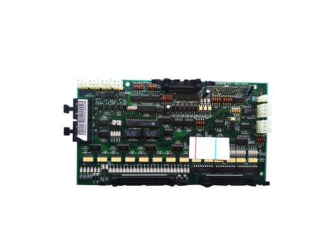
In some cases, a combination of through - hole and surface - mount mounting may be used on a single PCBA. For instance, power - related components that require a robust connection may be through - hole mounted, while signal - processing components can be surface - mounted to take advantage of the higher density and better electrical performance. The choice of component mounting method depends on factors such as the component type, electrical requirements, board size, and manufacturing cost.